- WEMScontroller3.
- Run Channel Setup Wizard To Configure Analogue Outputs.
- Run Channel Setup Wizard to configure analogue inputs.
- Run AHU Discover Wizard.
- Configure AHU Control Points.
- Assign A Schedule To The AHU.
This guide covers the first-time setup of an AHU, and assumes that a WEMScontroller3 has already been through and had its analogue outputs set up.
- Select the channel type as Analogue Input in order to configure the inputs.
Any analogue inputs could be used at this point, i.e. it's not essential to use the analogue inputs of the WEMScontroller3; however, as the device has 2 spare analogue inputs, it's easiest to use them for this purpose.
- Select Multifunction Sensor 1, and then click .

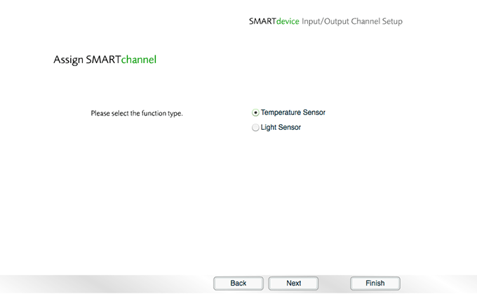
- Select Temperature Sensor, and then click .
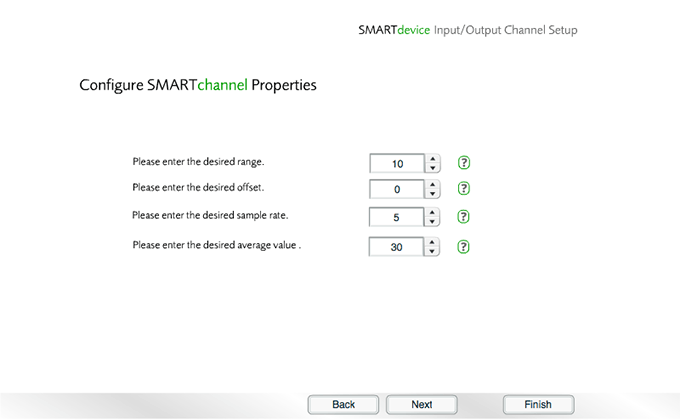
- Choose the properties for the channel, and then click .
![]() View/hide
channel property definitions
View/hide
channel property definitions
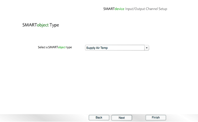
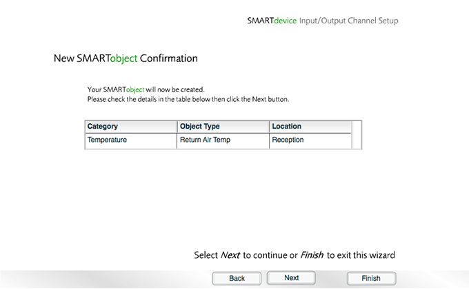
- Set the Object type to Supply Air Temp, and then click .
- Choose a location, and then click .

- Click to the confirmation message.
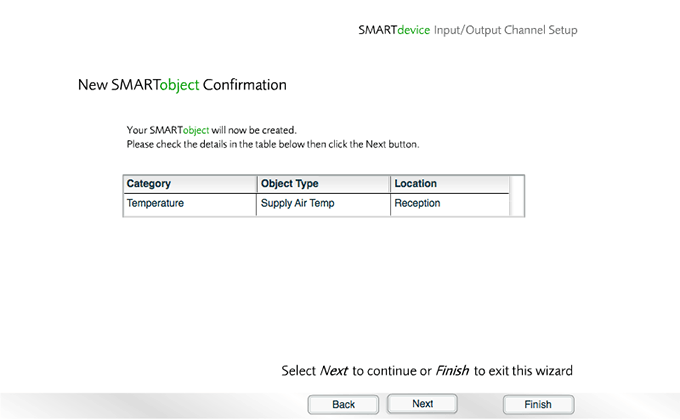
- Click to begin configuring the next channel.
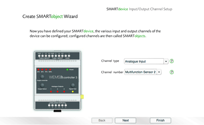
- Set the channel type to Analogue Input.
- Select Multifunction Sensor 2, and then click .
- Select Temperature Sensor, and then click .

- Choose the properties for the channel, and then click .
![]() View/hide
channel property definitions
View/hide
channel property definitions
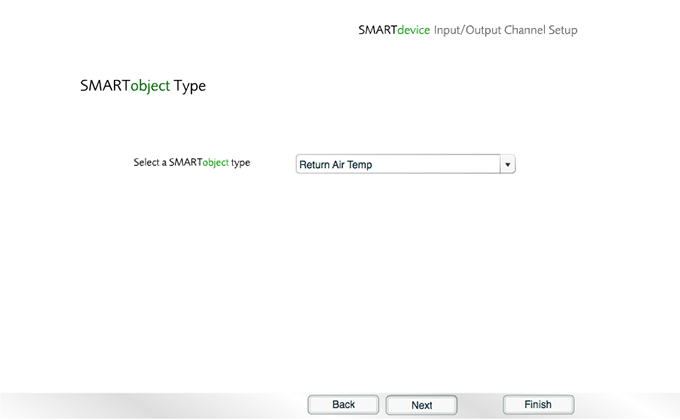
- Set the Object type to Return Air Temp, and then click .
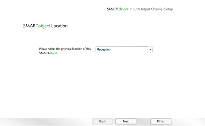
- Choose a location, and then click .
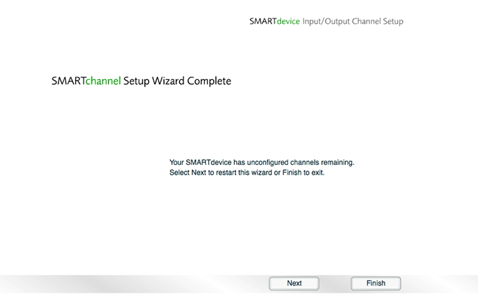
- Click to the confirmation message.
- Click to exit the wizard.
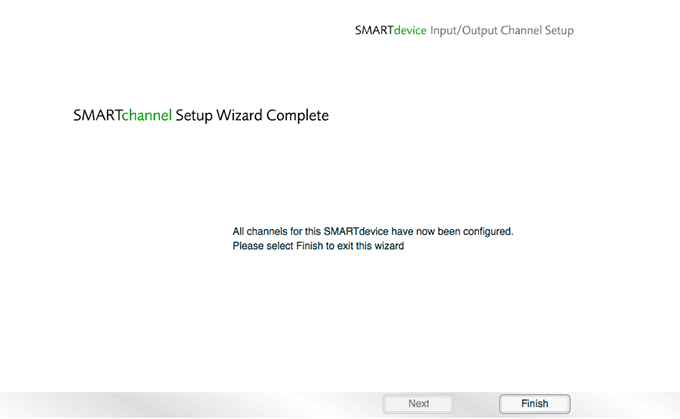
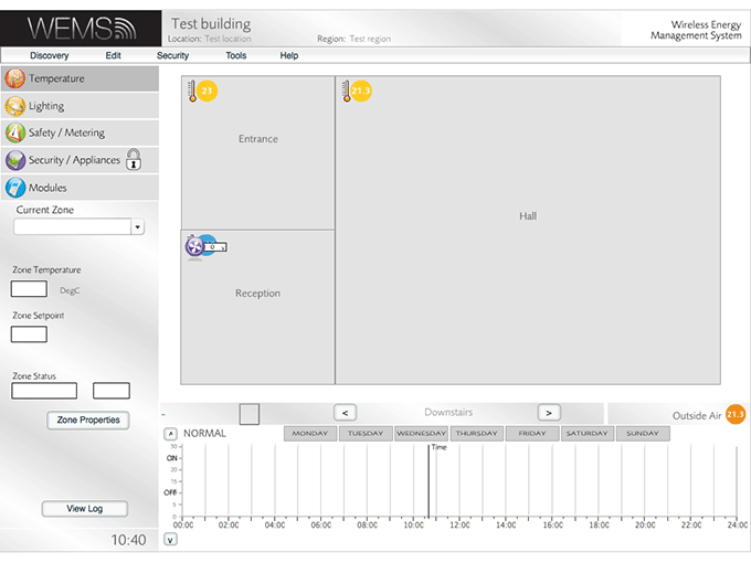
The Channel Setup Wizard is now complete and control is returned to the Floorplan.
In order for the AHU to function, the system will need to be configured with an Outside Air Temp sensor. A wireless outside air sensor is required for this role (e.g. the ASD09N4O or ASD09N4OL), which can be discovered and configured via the usual Auto Discover wizard.
Before moving on to run the AHU Discover Wizard, it's recommended to hide the extraneous new icons that will have appeared on the Floorplan. If this is not immediately apparent, exiting and re-entering the user interface will cause the Floorplan to refresh and display the new icons. To remove the extraneous icons, do the following:
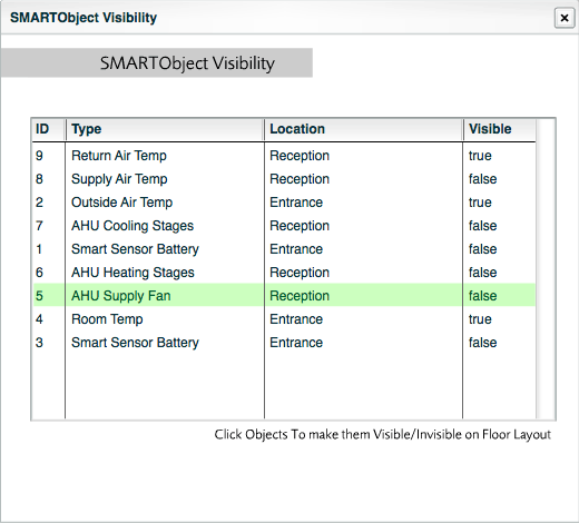
Go to | , and hide all AHU-related items except for Return Air Temp, as this is the only value that is likely to be of interest once the AHU is operational. Hide the following items by clicking on them to set their value to false:
- AHU Cooling Stages
- AHU Dampers (if present)
- AHU Heating Stages
- AHU Supply Fan
- Supply Air Temp
Next Step
The and Channel Setup of the WEMScontroller3 is now complete.
The next step is to Run The AHU Discover Wizard.