This section covers how to view and edit the settings of a typical FP AHU.
If you have yet to set up the FP AHU for the first time, see the FP AHU First-time Setup guide.
To view and edit an existing FP AHU's settings, click the FP AHU icon on the Floorplan, in the Temperature Layer.
![]()
FP AHU icon
The FP AHU Control Screen will appear.

FP AHU with control points defined and settings saved
FP AHU Status And Reference Temp
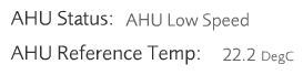
FP AHU status and reference temperature
The FP AHU's current operating status is shown in the AHU Status field in the top-left corner of the diagram. For a list of all possible statuses, see FP AHU Control Status.
The FP AHU's current reference temperature is shown in the AHU Reference Temp field in the top-left corner of the diagram. This value is set by the active Temperature Mode.
Alarms
The alarms shown on the Control Screen are as follows:
| Damper Alarm | if the unit is in free cooling and the Supply Air is 10° above Outside Air then the damper may not be open or faulty |
| DX Minor | if the unit is in DX cooling and the Supply Air is 5–10° below Return Air then DX may not be working properly |
| DX Major | if the unit is in DX Cooling and the Supply Air is less than 5° below the Return Air then DX is not working properly |
| Smoke Detect | If the Smoke Detection digital input is high then an alarm is highlighted and the unit will be in Smoke Detection mode |
Editing Control Points
To edit any control points, click the button,
adjust the dropdown selections accordingly, and then click . ![]() More
information …
More
information …
The topmost slot of the 4 Space Temp dropdowns must be populated in order for the room space temperature to act as a valid temperature reference. Filling the other 3 slots can allow the system to use temperature averaging, depending on which Temperature Mode has been selected.

Set the FP AHU control points
FP AHU Info Panel And Advanced Panel
The FP AHU Info Panel and Advanced Panel are used to manage the FP AHU setup. The Info Panel is found in the bottom-left corner. The Advanced Panel is accessed via the button at the bottom of the Info Panel (moderator password required). The Advanced Panel contains all of the settings available in the Info Panel plus some further settings.
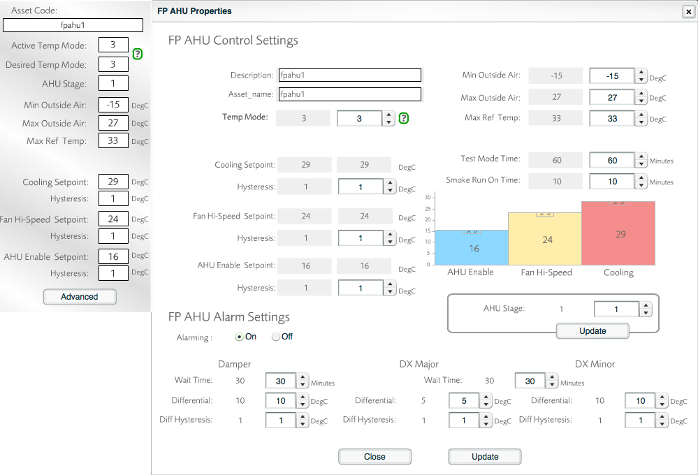
The settings of the Advanced Panel are as follows:
| FP AHU Control Settings | |
|---|---|
| Description | Description of the FP AHU Object |
| Asset Name | Unique customer reference number for the FP AHU |
| Temp Mode | One of 4 Configurable Modes (and 1 fail-safe mode that is not configurable) of control regarding which temperature sensor(s) thewill control against in certain situations. The system may change to a different temperature mode if the choice configured by the user is not achievable. For more information, seeTemperature Modes. |
| Cooling Setpoint | The cooling will enable when the reference temp is above this setpoint |
| Hysteresis | How many degrees the temperature has to drop below setpoint to disable cooling |
| Fan Hi-Speed Setpoint | The temperature at which the system will allow the FP AHU fan to operate at full speed. |
| Hysteresis | Once the strategy has enabled the fan to run at full speed it will not switch it off until the temperature has fallen below the Fan Hi-Speed Setpoint value minus this hysteresis value, e.g. if Fan Hi-Speed Setpoint = 24°C and Hysteresis = 1°, the fan will disable at 22.9°C. |
| AHU Enable Setpoint | The FP AHU will enable when the reference temperature is above this setpoint |
| Hysteresis | How many degrees the temperature has to drop below setpoint to disable the FP AHU |
| Min Outside Air | If the WEMS outside air temperature is below this setpoint then WEMS disable the DX Inhibit and the FP AHU controls to its own settings |
| Max Outside Air | If the WEMS outside air temperature is above this setpoint then WEMS disable the DX Inhibit and the FP AHU controls to its own settings |
| Max Ref Temp | If the WEMS reference temp temperature is above this then WEMS disable the DX Inhibit and the FP AHU controls to its own settings |
| Test Mode Time | The length of time for which Test Mode is active |
| Smoke Run On Time | If Smoke Detect Alarm is active and then clears, this is the number of minutes it will run on the fan before going back to normal settings |
| AHU Stage | Four pre-defined default AHU Enable and Cooling Setpoints for the unit. Stage 1 has the lowest setpoints and Stage 4 has the highest |
| FP AHU Alarm Settings | |
| Alarming | Enable or disable alarms |
| Damper: Wait Time | If damper alarm setpoints have been breached, this is the amount of minutes it will wait before it sends the alarm |
| Damper: Differential | The number of degrees that the Supply Air Temp is above the Outside Air Temp before a damper alarm is generated |
| Damper: Diff Hysteresis | The number of degrees that the Supply Air Temp must be under the differential for the alarm to clear |
| DX Major/DX Minor: Wait Time | If DX alarm setpoints have been breached, this is the amount of minutes it will wait before it sends the alarm |
| DX Major: Differential | If the difference between Supply Air Temp and Return Air Temp is below this setpoint then an alarm is generated |
| DX Major: Diff Hysteresis | The number of degrees that the Return Air Temp must be above the differential for the alarm to clear |
| DX Minor: Differential | If the difference between Supply Air Temp and Return Air Temp is below this setpoint then an alarm is generated |
| DX Minor: Diff Hysteresis | The number of degrees that the Return Air Temp must be above the differential for the alarm to clear |
Manual Override

No manual override

Manual override activated
The button at the top of the screen is used to put the unit back into fail-safe mode. This stops all control by the system over the FP AHU and reverts it back to its normal control strategy, as if the WEMS equipment were not there.
Test Mode
When the button is pressed, another button labelled Test Mode appears at the top of the screen. This button allows engineers the ability to test the relay digital outputs to see whether they are wired and operating correctly. This is a useful test to conduct when commissioning the unit and helps to highlight any wiring issues or faults with the physical units themselves.
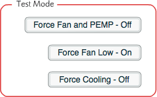
Options presented in Test mode