This example shows how to use the Channel Setup Wizard to configure a room temperature sensor.
- Launch the Channel Setup Wizard, either by clicking the button at the end of the Auto Discover Wizard or by clicking the button in the Modules Layer.
The Channel Setup Wizard can be used only after a device has first been detected. For a guide on how to detect the sensor, see Detect A Battery-Powered Sensor Via via .
- Choose the channel type as Analogue Input and the channel number as Temperature Sensor, and then click next.
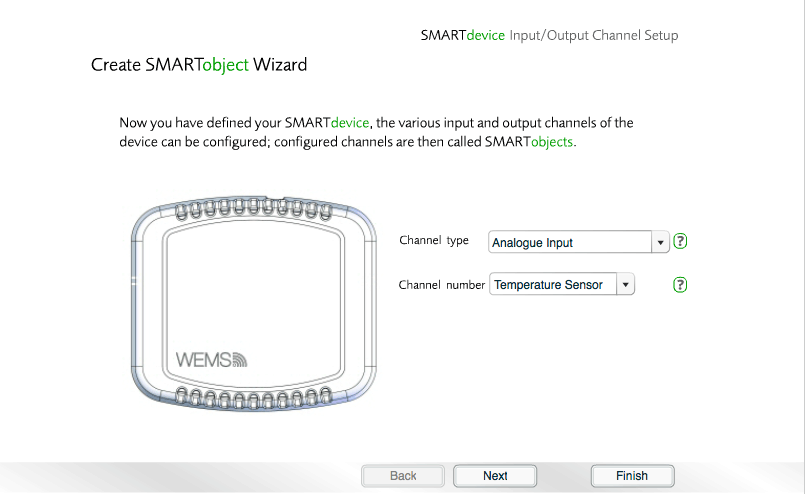
The Channel Setup Wizard room temperature example – choose the channel type and channel number
- Choose the properties for the channel, and then click .
![]() View/hide
channel property definitions
View/hide
channel property definitions
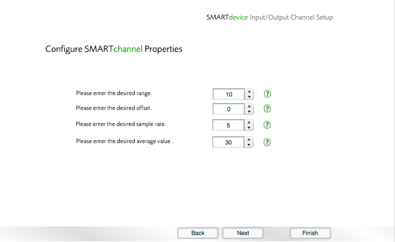
Choose the channel properties
- Choose the type of reading measured by the sensor, and then click .
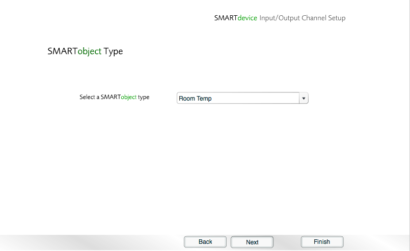
Choose the type of measurement
- Now choose the location of the device, and then click .
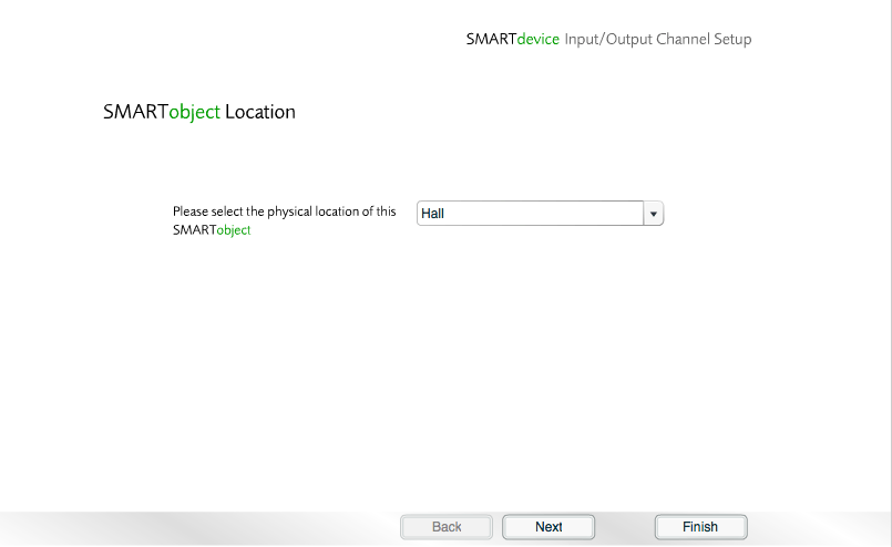
Choose the location of the device
- The wizard will now display a confirmation of the chosen options. Click to continue.
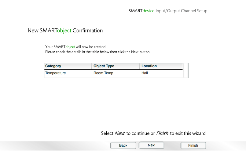
A summary of the options chosen
- Select any Objects to link to the sensor, and then click Next.
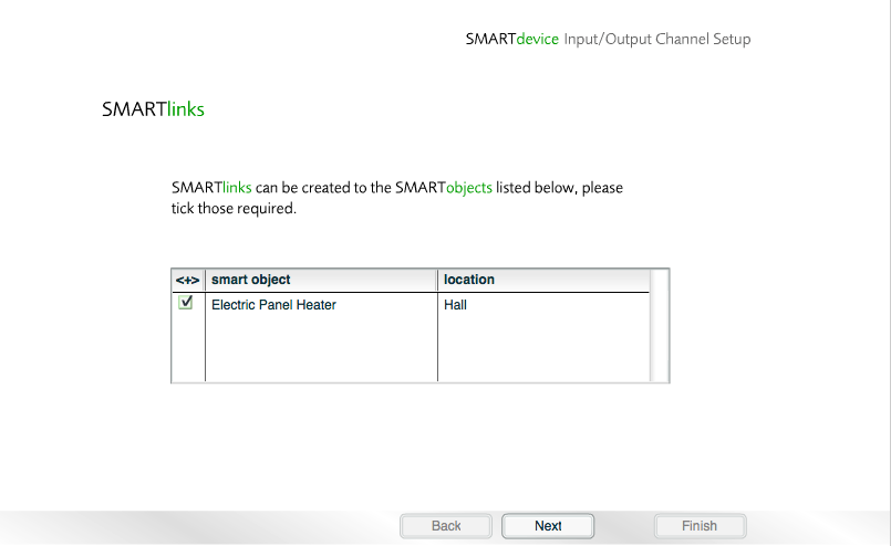
Link Objects to the sensor (screen not shown if no Objects are available for linking)
The Channel Setup Wizard is now complete.
If the device has any channels that have not yet been configured, you will be given the option to re-run the Channel Setup Wizard in order to configure those channels. You may either run the Channel Setup Wizard again now or return to it at a later stage, via the button in the Modules Layer.
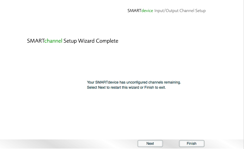
Final screen of the Channel Setup Wizard
Click to return to the Floorplan. The temperature sensor will display a reading when viewed on the Temperature Layer.
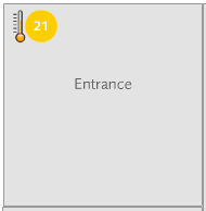
The temperature sensor shown on the Floorplan