This section covers how to view and edit the settings of a typical VT Circuit.
If you have yet to set up the VT Circuit for the first time, see the VT Circuit First-time Setup guide.
To view and edit the settings of an existing VT Circuit, do the following:
Click the VT Circuit icon on the Floorplan, in the Temperature Layer.
![]()
The VT Circuit icon
The VT Circuit Control Screen will appear.
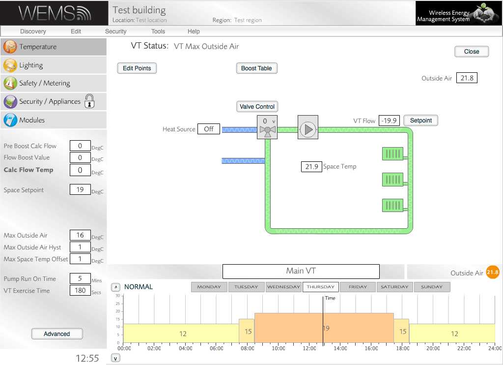
VT Circuit Info Panel And Advanced Panel
The VT Circuit Info Panel and Advanced Panel are used to manage the VT Circuit setup. The Info Panel is found in the bottom-left corner. The Advanced Panel is accessed via the button at the bottom of the Info Panel(moderator password required). The Advanced Panel contains all of the settings available in the Info Panel plus some further settings.
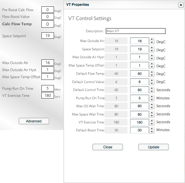
VT Circuit Info Panel (left) and Advanced Panel (right)
The settings of the Advanced Panel are as follows:
| Max Outside Air | Determines the temperature at which the VT Circuit strategy will inhibit the heat supply (regardless of internal space temperatures). |
| Space Setpoint | Determines what space temperature the VT Circuit is trying to achieve. |
| Max Outside Air Hyst | Once the VT Circuit has been disabled due to Max Outside Air Temp – this value determines how many degrees below the current Max Outside Air Temp the outside air needs to be before the VT Circuit will enable again. E.g. if the Max Outside Air is 16° and the Max Outside Air Hyst is 1°, then once the outside air temp rises above 16° the VT Circuit will disable and will not be allowed to re-enable until the outside air temp falls to 15° (strictly speaking it will be 14.9°). |
| Max Space Temp Offset | The number of degrees centigrade above setpoint where the VT Circuit will disable. The setpoint is effectively raised by this amount (default 1°). This means that when the space cools down, there is a longer wait before needing to turn on the VT Circuit again (prevents short cycling). |
| Default Flow Temp | Used when the Outside Air Temp is unknown. Sets a default calculated flow temperature. |
| Default Control Value | Determines the default voltage applied to the heating valve should the boiler flow temperature be unknown. |
| Default Control Time | Determines the default time to wait before re-processing the calculated flows, etc. |
| Pump Run On Time | Determines how long the VT Circuit strategy runs the pump for when the VT Circuit is shutting down. This allows the circuit to dissipate any residual heat from the boilers after they have been switched off, in order to prevent over-heat lockouts. |
| Max OS Wait Time | Determines the time to wait before re-processing calculated temperatures, etc. once the VT Circuit strategy has entered Max Outside Air mode. |
| Max Space Temp Wait Time | Determines the time to wait before re-processing calculated temperatures, etc. once the VT Circuit strategy has satisfied the desired space setpoint. |
| VT Exercise Time | On startup the VT Circuit strategy will simply run the pumps of the VT Circuit to generate flow and to ensure there are no problems with the plant (this is called the 'exercise time'). Once completed the VT Circuit strategy will then start to control as normal. |
| Default Boost Time | Should the strategy apply a particular voltage onto the valve to achieve a particular flow temperature but after leaving the voltage applied the flow cannot reach this setpoint then the calculated flow temperature is boosted (which should in turn up the voltage applied to the heating valve). This setting determines the default time to keep a boost on the calculated flow temp. |
Edit Points
The main part of the VT Circuit Control Screen contains a diagram to illustrate the setup of the VT Circuit. To edit the reference points that are used to control the VT Circuit, click the button in the top-left corner of the diagram. The screen will then change to look like the one shown below.
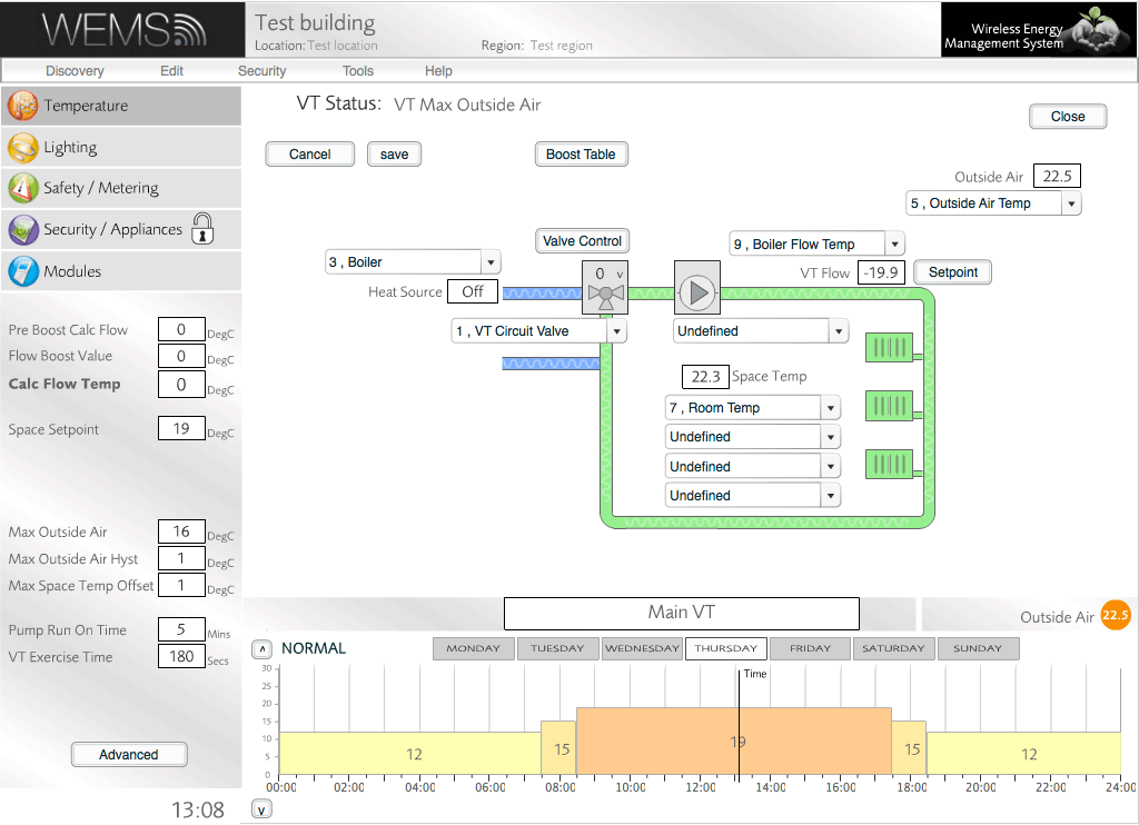
As shown, a series of dropdown menus appear that allow the user to change the references (or control points) that are used to control the VT Circuit. Although there will typically be no need to change these settings after the initial setup, there may be occasions where changes to the Outside Air Temp reference or the Space Temp references are required.
Control Point Graphs
For fine control over the boost, valve and setpoint settings, use the relevant buttons in the main diagram. An administrator password (not the same as the login password) is required to change the settings, but it's possible just to view the settings without entering the password, by clicking the button. Some example graphs are shown below.
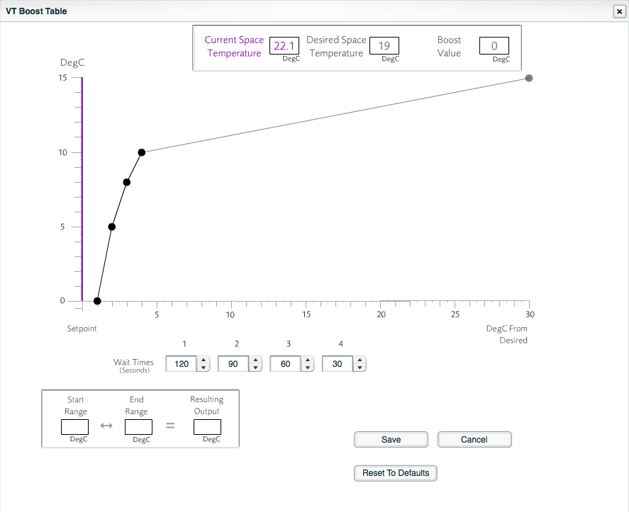
Boost Table graph
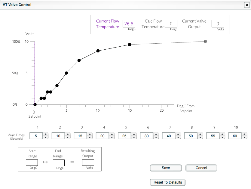
Valve Control graph
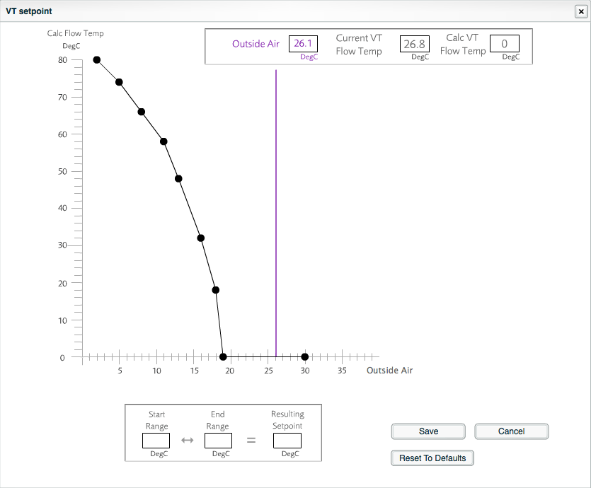
Setpoint graph
The graphs can be modified by dragging the control points (black circles). Whenever the cursor hovers over one of the points, the value to which that point refers is highlighted on the graph. The corresponding wait time for that point on the graph is also highlighted in the relevant box below the graph.
Below the wait times is a box that confirms the ranges that apply to the currently highlighted control point on the graph. The values indicate the lowest and highest temperatures that apply to the currently highlighted control point and the resulting voltage that will be used for that control point.
Any inadvertent changes to the settings on these screens can be reversed by closing the window without clicking the button. There is also an option to go back to the default settings, via the button.