This section covers how to view and edit the settings of a typical FanCoil.
If you have yet to set up the FanCoil for the first time, please see the FanCoil First-time Setup guide.
To view and edit an existing FanCoil's settings, do the following:
Click the FanCoil icon on the Floorplan, in the Temperature Layer.
![]()
The FanCoil icon
The FanCoil screen will appear.
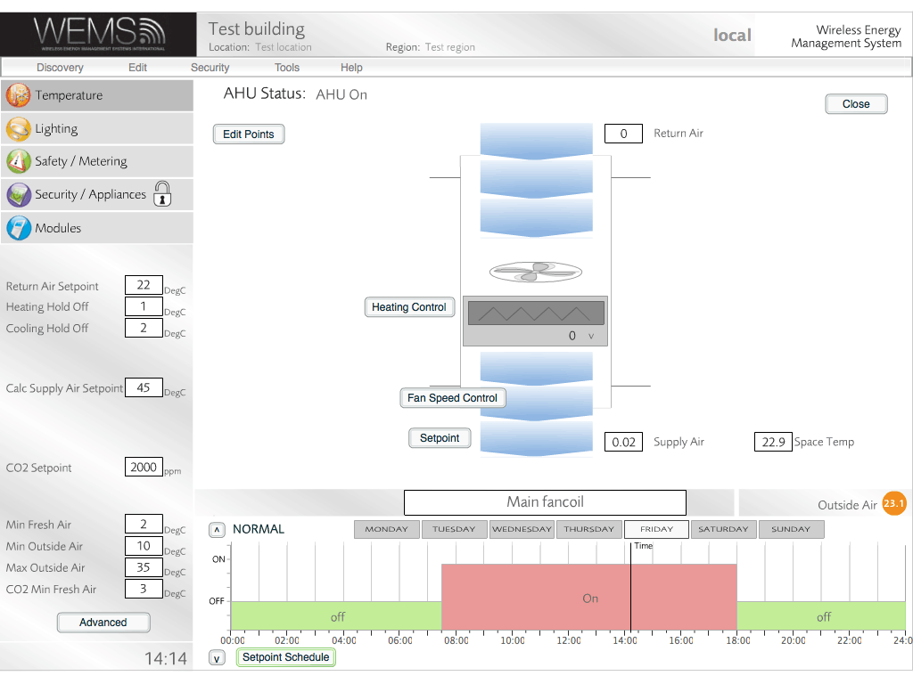
FanCoil screen
FanCoil Info Panel
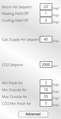
FanCoil Info Panel
The FanCoil Info Panel is used to manage most of the settings that control the operation of the FanCoil. The Info Panel is found in the bottom-left corner of the main FanCoil screen and looks like the image to the left.
The settings of the Info Panel are as follows:
| Return Air Setpoint | The desired temperature of the air leaving the system |
| Heating Hold Off | TBC |
| Cooling Hold Off | TBC |
| Calc Supply Air Setpoint | The calculated temperature that air entering the system needs to be in order to achieve the desired room space temperature |
| CO2 Setpoint | Used to control maximum parts per million of CO2 – this determines how the dampers work to make sure that fresh air comes in |
| Min Fresh Air | Voltage setting on the dampers to ensure that at least some fresh air still comes in |
| Min Outside Air | Minimum temperature at which dampers can open fully |
| Max Outside Air | Maximum temperature at which dampers close fully so that internal air can be cooled |
| CO2 Min Fresh Air | If CO2 Setpoint threshold is reached, this value sets the voltage to apply to dampers (increase value to open dampers more) |
FanCoil Advanced Panel
To access the Advanced Panel, click the button at the bottom of the Info Panel. Because of the nature of these settings, a warning window is displayed when the button is clicked. An administrator password (not the same as the login password) is required to change the settings, but it's possible just to view the settings without entering the password, by clicking the button.
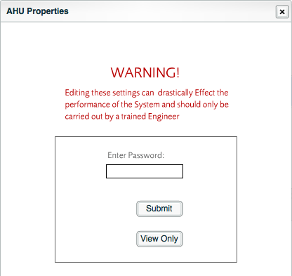
A warning is displayed
In this example, the password has been entered and so the settings below could be changed.
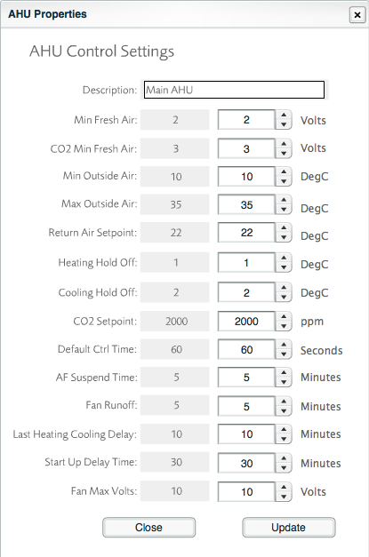
FanCoil Advanced Panel
The settings of the Advanced Panel are as follows:
| Min Fresh Air | Voltage setting on the dampers to ensure that at least some fresh air still comes in |
| CO2 Min Fresh Air | If CO2 Setpoint threshold is reached, this value sets the voltage to apply to dampers (increase value to open dampers more) |
| Min Outside Air | Minimum temperature at which dampers can open fully |
| Max Outside Air | Maximum temperature at which dampers close fully so that internal air can be cooled |
| Return Air Setpoint | The desired temperature of the air leaving the system |
| Heating Hold Off | TBC |
| Cooling Hold Off | TBC |
| CO2 Setpoint | Used to control maximum parts per million of CO2 – this determines how the dampers work to make sure that fresh air comes in |
| Default Ctrl Time | Length of time to wait before making further changes |
| AF Suspend Time | Shuts unit down if no air flow detected for more than the set value |
| Fan Runoff | Runs the fans for the set length of time after heating coils are turned off, to avoid overheating |
| Last Heating Cooling Delay | Delays cooling for the set value to make sure the system does not go into a heating-cooling-heating cycle |
| Start Up Delay Time | Lets fans run for the set time before control begins |
| Fan Max Volts | Sets maximum speed for fans (as long as they are controlled via analogue 3-way outputs) |
Edit Points
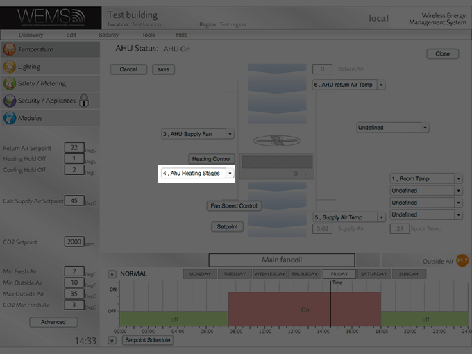
The main part of the FanCoil screen contains a diagram to illustrate the setup of the FanCoil. To edit the reference points that are used to control the FanCoil, click the button in the top-left corner of the diagram. The screen will then change to look like the one shown below.
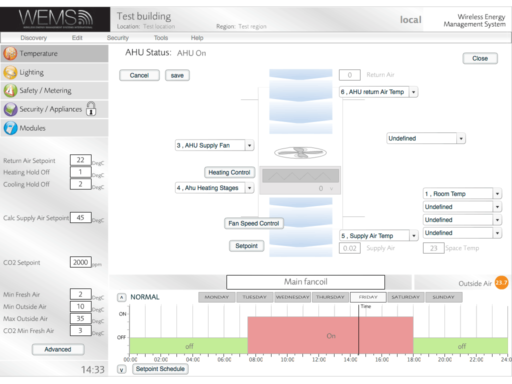
FanCoil Edit Points screen
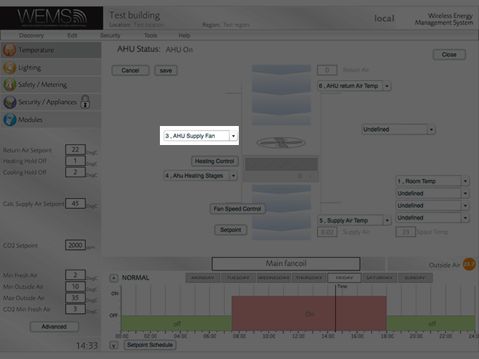
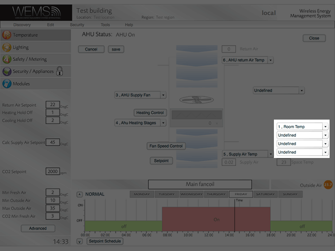
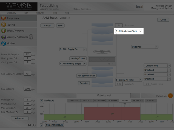
As shown, a series of dropdown menus appear that allow the user to change the references (or control points) that are used to control the FanCoil. Although there will typically be no need to change these settings after the initial setup, there may be occasions where changes to the Space Temp references are required.
![]() Click here to see each control point highlighted individually.
Click here to see each control point highlighted individually.
Control Point Graphs
For fine control over the fan and AHU Heating Stages, use the relevant and buttons in the main diagram. An administrator password (not the same as the login password) is required to change the settings, but it's possible just to view the settings without entering the password, by clicking the button. Some example graphs are shown below.
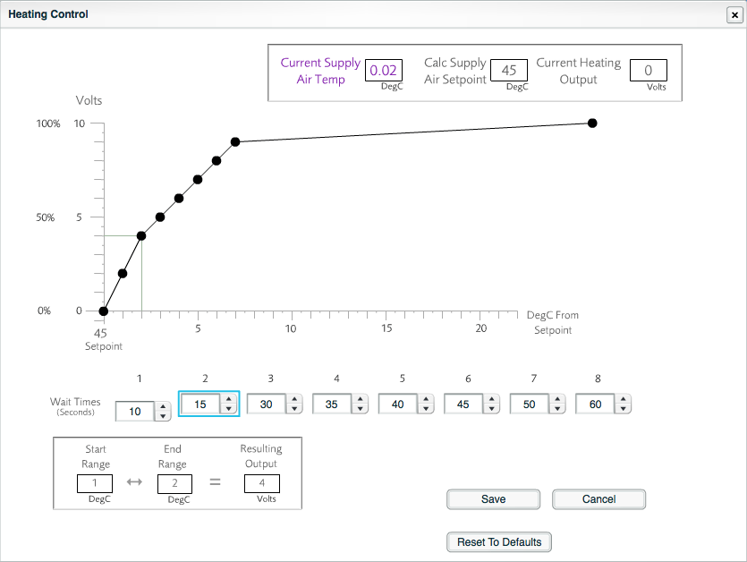
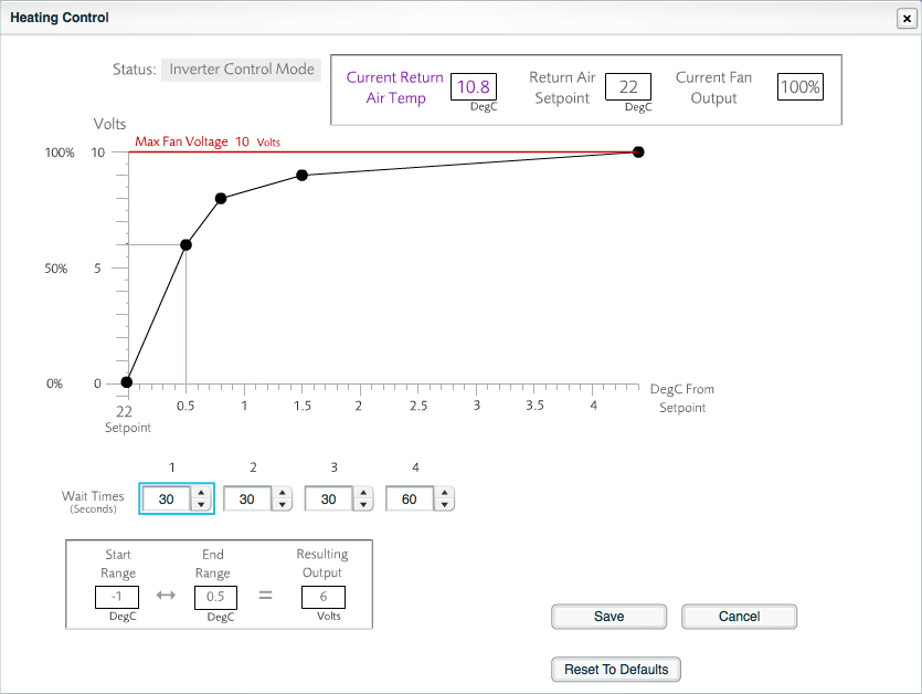
The graphs can be modified by dragging the control points (black circles). Whenever the cursor hovers over one of the points, the value to which that point refers is highlighted on the graph. The corresponding wait time for that point on the graph is also highlighted in the relevant box below the graph.
Below the wait times is a box that confirms the ranges that apply to the currently highlighted control point on the graph. The values indicate the lowest and highest temperatures that apply to the currently highlighted control point and the resulting voltage that will be used for that control point.
Any inadvertent changes to the settings on these screens can be reversed by closing the window without clicking the button. There is also an option to go back to the default settings, via the button.
